Bioelectrical impedance analysis provides information relating to the human body's state of nutrition and hydration. It is not surprising that bioimpedance monitors are now widely used in chronic renal disease patients. Two excellent editorials recently published in Nefrología reviewed available bioimpedance systems and the clinical information that we can obtain from them.1,2 However, gaining a basic understanding of bioimpedance may be difficult for a doctor whose notions about electricity are limited to high school courses taken many years before. This editorial provides a review of the electrical principles needed in order to understand how a bioimpedance monitor works.
Alternating current electrical circuits are defined by four parameters: current, voltage, impedance and oscillation frequency. Impedance refers to the opposition that a circuit presents to the passage of a current, measured in Ohm. The unit for measuring electric current is the Ampère; voltage is measured in Volt and frequency in Hertz (cycles per second). The fundamental law of electricity relating impedance with current and voltage is Ohm's law: impedance=voltage/current.
When alternating current circulates through a medium, impedance depends partially on the medium's ability to conduct current, and it is proportional to the electrical resistivity or poor conductivity of that medium. If an electrical circuit also contains capacitors (systems made up of metal foils separated by insulating film where energy is stored, and which discharge energy when the system becomes saturated), impedance will also depend on the number of capacitors through which the current must pass, and on their charging and discharging capacity. The impedance component (Z) resulting from poor conductivity of the medium is called resistance (R) and the component resulting from the action of the capacitors is known as capacitive reactance (Xc), or simply reactance for purposes of this paper. The equation relating these concepts is:
(Z)² = (R)² + (Xc)² (equation 1)
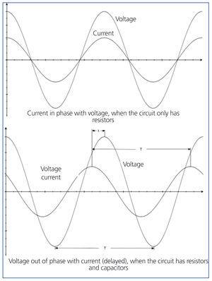
The behaviour of an alternating current circuit is defined by 2 waves having different amplitudes, but the same frequency: the current wave and the voltage wave. If the peaks of both waves coincide, we say that the current is in phase with the voltage. When the circuit contains capacitors, their charging and discharging processes slow the voltage wave with respect to the current wave, and the current is said to be out of phase. This phase difference is given as an angle, called the phase angle (φ) (Figure 1). The tangent of φ is Xc/R (equation 2).
Bioimpedance represents the resistance offered by a biological medium to the flow of alternating current, and it contains the components of resistance and reactance mentioned previously. Resistance depends on the resistivity of different tissues to conducting electrical current: bone and fatty tissues are poor conductors, and current flows better through intra- and extracellular fluids, which are electrolytic solutions. Reactance is produced due to the insulating effect of cell membranes, which act as capacitors to store energy and discharge as the current passes through them.
The most common bioimpedance system is the whole body analysis (4 electrode method): two electrodes are placed on a lower limb (top of the foot and ankle) and the other two on an upper limb (back of the hand and wrist). Stable, very low alternating current flows between the distal electrodes (measuring a few tens or hundreds of microamperes). The monitor reads the voltage between the proximal electrodes (Figure 2). It reads the voltage and the current, and is able to detect the difference (phase angle) between both values. Using Ohm’s law, it calculates impedance from the voltage and the current. Using equations 1 and 2, the monitor calculates resistance and reactance from impedance and the phase angle.3,4
Resistance, reactance and phase angle values all depend on the alternating current frequency. Resistance is inversely proportional to frequency, since the electrical conductivity of most tissues increases along with frequency. The relationship between reactance and the phase angle is a parabolic curve: the maximum values are obtained at frequencies approaching 50kHz and decrease as the frequency departs from that value, regardless of whether it increases or decreases.5 The frequency of alternating current is a key factor for interpreting the bioelectrical values that are given. Some bioimpedance monitors use 50kHz as their sole frequency, while other monitors read and calculate bioelectrical parameters using multiple frequencies.
The monitor’s computer system uses a set of equations to calculate values for body volume and mass based on the electrical data. These predictive equations include other variables, such as weight, height, age and sex; most do not include the reactance component.3,6-10 These equations have been validated against the methods of reference for measuring different components of the human body.7,9-11 Each monitor uses different equations depending on the bioimpedance system, the theoretical analysis models and the method of reference chosen to validate measurements. These equations are often hard to obtain. Presenting bioimpedance results as body volumes and masses is called conventional bioimpedance analysis. Another way of expressing bioelectrical data is to construct an impedance vector using the resistance and reactance obtained at a frequency of 50kHz (vector bioimpedance). By comparing this vector with that of a healthy population, we obtain information about the individual’s state of hydration and nutrition.3
In conclusion, we can state that current, voltage and phase angle are the three main electrical parameters with which the monitor works. Using these parameters, the monitor calculates impedance and its two components, resistance and reactance. Different body volume and mass values are calculated with predictive equations, based on the electrical parameters and other patient data.
Conflicts of interest
The authors affirm that they have no conflicts of interest related to the content of this article.
Figure 1. Voltage and current in alternating current circuits
Figure 2. Diagram of a 4 electrode bioimpedance model


